3D Modelling a Revolver - Part 2
- Sep 30, 2020
- 9 min read
With another weeks comes more modelling. I've decided to post about this each day I work on the model, as I like to get a lot down in a short amount of time. So, without further ado, here's how I've progressed in modelling my revolver since last time.

I've already modelled the metal connector and handle, so I decided that next I would model the trigger and its guard, I originally decided that I wanted to use a pipe and then extrude it out and along the top of the previous model.


I originally went about this by creating a pipe primitive and getting it into position before deleting all but the top faces. I elongated the pipe to match the curve of the trigger guard better, which I still had to adjust quite a bit to fit it perfectly.


I then disbanded and rotated parts of the geometry to match the straight edge along the bottom of the guard. I did the same across the top with the plan to move the vertices up there forward to create the shape more convincingly.


Since the vertices didn't all line up and there was a gap between two of them, I started to have doubts about this method. Since I hadn't completely thought this stage through, I knew I'd made a mistake. I initially tried to extrude some more faces out to try and create the rest of the shape, but that didn't work either.
So, I brainstormed a new plan. I realised that I had been overcomplicating things once again, and that all I needed to do was follow the shapes that were already there. I quickly saved my first attempt at the trigger to a separate layer and turned the visibility off.


So I started fresh with a brand new pipe. I gave it similar measurements to the original one I'd used, before elongating it. This time, I decided to rotate it so that it lists slightly to the left, which follows the curve of the guard far more accurately than the first attempt did. I deleted all the bottom and side faces so that it would be easier to edit.
I used the same technique to flatten out the bottom part of the ring (by disbanding it with the scale tool), before pressing 3 to view the smoothed version of it and adjusting the rest of the vertices to follow the curve.
I had to be careful in how I positioned these points, as the image I have as reference isn't laying flat on a surface and has different perspective. Because of this, some parts of the trigger are visible when they shouldn't be. I'm certain that I've definitely gone over some of the lines with this component of the model, as the metal is shiny and sometimes can be hard to decipher because of the reflection bouncing up onto the shaded side.


Once I'd decided I was happy with how the geometry looked, I selected it and extruded it outwards to the same thickness as it had originally been. Since polygon primitives expand from the middle and extrusions expand from an edge (only on one side) I had to double the size I originally had to get the measurements correct.
I then moved the geometry back into the centre of the scene. I did this by adding an edge loop right in the centre of the pipe and then snapping the object's orientation to it, and then centring it with grid snapping. This edge loop will also help the pipe keep more of its shape when smoothed.
With the pipe centred, I created a cube and adjusted and sized it into the correct position. Since I didn't delete any faces on it, I had to be mindful to move before vertices while adjusting it.


With the cube in the right position, I free-handed some edge loops to the edges of where the pipe will connect to it. I did this again for the other edges of the pipe as well, before adding one final edge loop to the centre of the of the cube. This will be where the hole in which the trigger pokes through. I thought it was import to establish this before I started bevelling all the edges of the geometry.
I combined both shapes, and snapped the vertices to each other to make combining smoother. I made sure to delete the faces the cube had inside the vertices before merging them, as there's no need for geometry inside a solid object.

This is what the trigger guard looks like right now. With it combined and merged, it was time to bevel it.


I bevelled all the way around the edges around the cube, and then bevelled the pipe separately. I did this so that I could make the pipe smoother than the cube, as its far more curved than the cube part of the trigger guard is. I made sure to select the edges connecting the pipe to the cube, so that they wouldn't lose any definition on the bottom of it.


For now, this is the finished trigger guard. Since this is now as complete as it can be for the moment, it was time to make the actual trigger to sit inside.
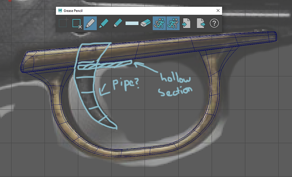
I used the grease pencil tool to plan out how I would go about modelling this. I decided that the easiest way to model the trigger would be to create another pipe, delete some of the faces and then adjust it until it fit in with reference.
I also made to mark out the hollow section of the trigger guard. I knew I'd have to delete the faces on the cube, but I decided to model the trigger first in case I needed to make any adjustments.


So I created another pipe and moved it into position and deleted all the faces that weren't going to be used. I then selected the vertices and moved them around until I was happy with the shape. I also had to make sure I selected both of vertices whenever I did this, as I kept this piece of geometry as a 3D shape, as that was far easier than deleting all the faces, extruding them out and moving them back to the centre.
Since this wasn't going to take long, I just kept it as it was, and filled the gaps on the bottom and top. I also made sure to model the trigger up to the screw in the metal connector, which is what holds it in place.


The final adjustment I made was on the bottom edges of the trigger. I cinched the edges in so that the trigger wouldn't look too sharp. With that down, I selected all the edges and bevelled them.
Like the pipe of the trigger guard, I made sure it wasn't too sharp, and still retained some of its curve. When I decided I was happy with the bevel, I moved onto creating the hollow space in the cube above.


While going to delete the faces on the trigger guard, I saw that the bevel had created a hexagon, so I used the multi-cut tool to correct the the geometry and create two squares. I then went ahead and deleted the faces on the cube and filled them in. I then bevelled the edges so that the hole didn't end up as a circular dip in the geometry.


I decided to make an indentation in the cube, so that I can later change the metal connector to fit inside it. I did this by selecting all the vertices on top apart from the edge-most ones and pushing them down and rotating them slightly. I also extruded the faces downwards to give it more of a noticeable different to the rest of the geometry.
I final thing I did was bevel the edges, before saving both the trigger and the guard into their own layer in Maya.


With the trigger and guard finished, here is what the revolver currently looks like. The next thing I decided to create was the hammer, which is highly similar in shape to the trigger. This is the reason I decided to make these two shapes in the same day, as I could use some of the same techniques I'd used previously for the trigger.
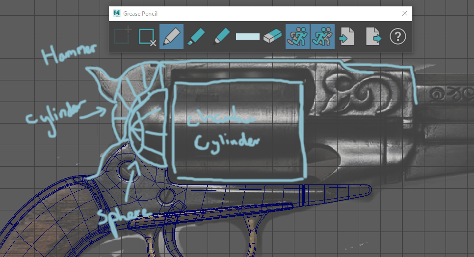
I once again used the grease pencil to plan out my next move, and decided that I would use a cylinder to create the hammer, with a extrusion to create the small lever off the side. I also marked out where the other metal connector (which sits under the first) would go, and how it needed to attach to the sphere in in the centre.
I also debated on whether this part of the revolver would be connected to the barrel. I've decided for the moment that it wouldn't, but this part will extend over the chamber/cylinder.


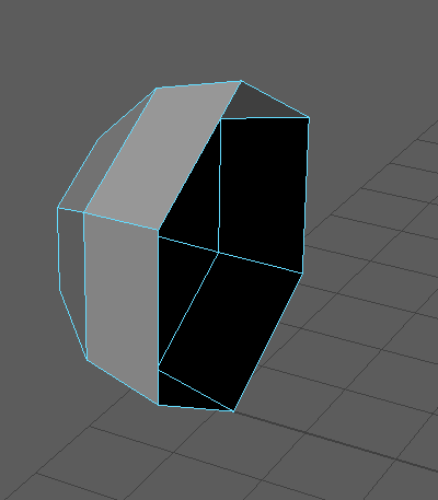
For now, I worked on the hammer. I created a cylinder and moved it into position. I found that rotating it helped, so I fiddled around with it to get it right. I decided while moving the vertices around that this part of the revolver should actually be a pipe, but instead of starting over, I just added a subdivision across the top and then deleted the faces I didn't need. Then, I filled in the hole and redrew the edges with the multi-cut tool.
Although this isn't the preferable way of doing things, it saved me the trouble of creating a pipe and getting the size and position right. I was also happy with how the vertices were positioned, and felt that I wouldn't be able to get this right a second time.


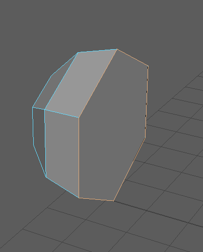
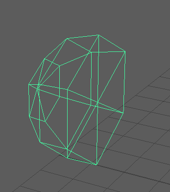
I then selected the face on the outside and extruded it outwards, adding three subdivisions to it. I played around with the position before finding a good balance. Since the hammer's lever is curved in multiple places, I worked hard to replicate this.


I bevelled the hammer all the way round, making it sharper than the trigger and guard. I didn't like how square the tip of the lever was, so I selected the bottom vertices and pushed them up and in to give it the ornate feel that it has in the reference. My opinion on older guns is that they were designed to not only be lethal but also to be beautiful and a symbol of how wealthy the owner was. With this in mind, I made sure to make the hammer more elegant with the final touches.


Here's how the revolver looks with the hammer. It gives a much better idea of what the revolver will look like when finished.

To myself in future, I create a cylinder to be a place-holder for the chamber. With modelling going smoothly, one of the next things I'll be modelling with be the the frame over the top of the chamber, so having something there of the same size to guide me is helpful.


Here's how the revolver looks with the chamber place-holder. It will be a very useful for future modelling.


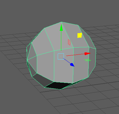
With a bit of time left, I decided to start on modelling the under metal part. I decided to use pipes to get the correct shape. I made sure that I remembered the amount of subdivisions I had used for these pipes, as I needed to attach a sphere to it. I created a sphere to test out how the the two pieces of geometry would fit together.


I realised I needed to move the vertices a bit to accommodate the sphere, so I moved them around a bit after deleting all the faces I didn't need off the pipes.

I then went back to the drawing board with the grease pencil and planned out how I would create the rest of this part of the revolver. I needed to delete some parts of it as well as extrude some.


I straightened out some of the vertices and extruded a few parts of it out. I went into smoothed view to get a better idea of how it would look. I also extruded a small part off at the top of the top pipe to match the edge of the frame. Later, this will be extruded upwards and over the chamber.


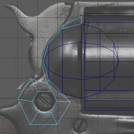
With the pipes combined and set up, I went to the sphere. I removed one side of it to make a semi sphere. I then filled in the hole and used the multi-cut tool to correct the geometry once more.


I checked the position of the semi sphere and realised that it was too far back to connect with the frame.


So I moved it forward and snapped the vertices to the corners of the sphere. After doing this, I decided it was best to stop modelling for the day. My next plans are to complete the frame of the revolver, and attach the sphere to it as well. I also need to make adjustments to the metal connector, which was the first thing I modelled.
Because of this, it doesn't fit perfectly with the rest of the models. I need to indent the bottom of it, as the trigger guard has to fit there as well. I also need to move the top vertices up to match the sphere, but this will need to be done after I've attached the sphere to the frame. I debated attaching the sphere to the connector, but I decided that it would be easier to attach it to the frame, as it goes all the way round the sphere.
Overall, the modelling has been going better than expected so far. I hope I can keep up the pace I have been, as it will leave me plenty of time to make changes and improvements to the model if I do.


Comments