3D Modelling a Revolver - Part 4
- Oct 9, 2020
- 6 min read
At the start of the fifth week of the project, I continued modelling my revolver. Where I left off last time was with the barrel just being modelled and a few design changed to the metal connector.

To start the day off, I went in with the grease pencil tool to plan out what I wanted to model today. Since I wanted to model the barrel, I decided create the other frame piece of the revolver was a good thing to do beforehand. Since the barrel follows the edge upwards, I decided it would be better to establish the line where it starts.


I used a cube and sized it to the correct shape, and then added 6 subdivisions on its height and 4 across its width. I made sure the edges over the divot were lined up perfectly so that I wouldn't have to worry too much about that.


I started moving the vertices around to fit the curve of the frame. I added two edge loops to help me get a better curve. On the other side of the cube, I adjusted the vertices to match the curve of the edge.


The last thing I did was move the edges of the frame up to match the edge on the reference image below. Now that I was happy with the basic shape of the frame, I added edge loops around the divot and then pulled the original edge inwards.


I then went in and evened out the topology on the frame, before straightening up the vertices with point snapping. I did this so that the top edge would be straight. Since this edge won't be visible, it made more sense to have it this way.


I took a few minutes to check that everything looked okay in 3D. I adjusted the size of the cylinder that runs through the chamber to help me resize the frame I had just created later.


I bevelled the edges of the frame by 0.09 with 2 segments. This matches nicely with the frame I made in the previous post, as the two are connected in the reference image. This makes it look nice and smooth, which matches the rest of the revolver.


I decided that the frame I was working on was too thick, so I disbanded it sideways so that it felt more 'anchored' by the rest of the revolver. I felt that it looked too big and made the gun look clunky. Although the revolvers I'm modelling after (belonging to Roland Deschain) are described as being comically large, so although this would've been appropriate, it didn't fit in with the rest of the models.
As a final adjustment, I moved the corner vertices downwards to make a more dramatic curve and then added bevels to the divot edges. I also gave this 2 subdivisions, but to the fraction of 0.07 instead, which makes it just the tiniest bit sharper.


With the under-frame finished, this is how the revolver currently looks.

Before I did anything else, I saved the barrel as its own layer, so that I could minimise it if I needed a better look at the reference beneath it.

I used the grease pencil tool once more to plan out how I would extrude the the edges downwards. Since there are different levels to the extrusion, the easiest way to model this would be to extrude it twice. Since I've already added the edge loops to the barrel, these will carry over to the extrusion.


Before I did any extruding, I duplicated the barrel to work from in case I found an easier way to go about things. I turned the layer visibility off and worked from the copy for this next part.
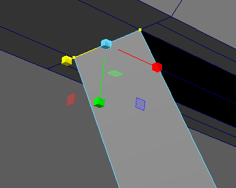
I selected all the bottom faces on the barrel and pressed Ctrl + E to extrude. I offset the extrusion area with the sizing tool, before hitting Ctrl E again to extrude only from that offset area. I pushed all of them downwards, matching where the first level ends.


I realised at this point that I didn't need to extrude all the faces along the barrel, just all of them apart from the last three. So I did the process again. When it came to the second extrusion, I offset the area further to present the difference in height they display in the reference image.


With the extrusions done, I adjusted where the furthest left vertices needed to be to help myself in positioning the others. Before I went any further, I added a final edge loop to the barrel's extrusion to create the tiny area depicted in the reference image. Since the vertical edge loop for this was already in place, I didn't have to fiddle around with anything just yet.


Since only some sections of the barrel are on the first level of the extrusion, I selected all the ones that weren't and extruded them backwards to line up with the second extrusion. This caused some of the faces to be incorrect, so I deleted them. The face on the 'front' of the barrel's extrusions had an edge that wouldn't line up correctly, so I deleted it. I then extruded the other side in the same way.


There were naturally a few problems with the various bevels, so I went in to fix them. A few of the edges had hidden faces, which I promptly deleted when I found them. I also found a few vertices in the middles of edges, which I couldn't quite figure out what to do with. I decided to worry about that one later, and instead selected all the edges in the area and merged them. Since the distance threshold is as low as it can be, the geometry as it appears won't be lost.

Here's how the barrel's looking so far in the front view perspective.


I used the multi-cut tool to fix the edges that I found earlier, which will need to be fully fixed later. Right now, the lines stop part-way up the cylinder, which I will fix once I've completed the extrusions.
I was having a lot of trouble with bridging the gap left in the front of the barrel, so I created a plain to use to fill in the gaps. I flipped it over to have it facing the right way, and changed the amount of subdivisions it had to match the hole I was trying to fill. I then moved it into position with grid snapping.

Once it was in the right place, I combined the two pieces of geometry and merged the vertices.


This concludes the barrel for now, but there are a few things I want to do before I commit to bevelling it.


The first small thing I did was mirror the metal connector and save it to its own layer. This makes the revolver far more convincing from the other side. These will need to be combined at some point, as it doesn't make much sense for them to be separate. It also doesn't look right for them to be individual pieces.

With that out of the way for now, I decided to move onto something else on the other side. On the frame, there should be an indent in the sphere so that the chamber can be accessed. I planned this out with the idea of creating new edges in the sphere and pushing the vertices inwards.


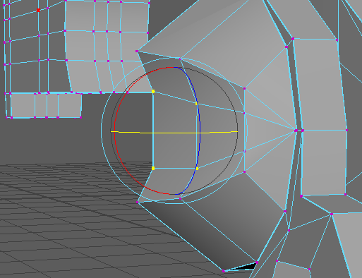


I started out with using the multi-cut tool to make cuts across the surface of the sphere. I then pushed these new vertices back, rotated them, and shrunk them down to fit them better into the sphere. I kept an eye on what it looked like smoothed, which was important.


I then did the same process again with some more multi-cuts. I played around with the bevelled edges as well, since I felt they needed to be moved somewhat.


Once I was happy with how it looked, I bevelled the edges. I played around with the vertices until I felt it created a smooth enough indent in the sphere.


Since some of the edge overlapped when I unsmoothed the selection, I had to go back and redo some of the adjustments I made.


Here's how my revolver is looking at the end of the day. It's really starting to come together now. Now that the majority of the models have been made, I have a good idea of what the finished revolver may look like. I still need to complete the barrel, create the chamber, and then add the details like screws and connecting up geometry.
This is also the point where I need to slow down, as making rash decisions on how to fix something without planning isn't something I should be relying on. Naturally, I do plan out my methods of fixing certain things, but since my knowledge of modelling and Maya is slightly lacking, I still make a lot of mistakes.
One thing that's apparent is that with the larger models done, the work I still need to do seems harder, as there is some guess work involved in this model. This is due to it being a fantasy gun, as well as having only a few reference images to work from. Some things will need to be changed before I can progress forward, which is what I hope to establish next time I work on this.


Comments