3D Modelling a Revolver - Part 5
- Oct 22, 2020
- 6 min read
In modelling, I decided it was a good time to try and create the chamber of the revolver. I didn't want to leave this too late, as I want to finish modelling the revolver with adding the details.
I decided to go with the third idea I had, which was to use the cylinder as a base for the modelling, and then model a cylinder into the same shape as it. Since I'm not a confident modeller, this was the easiest way for me to be able to achieve a convincing model.


I started by creating a copy of the cylinder I was using, and then creating a pipe. I changed the pivot point and snapped it to match the surface of the cylinder. This way, I could match the proportions of the cylinder perfectly.


I used the side view panel to help me line up the where the hole would be, and that it matched the size and position of the barrel. I then sized it down and decreased the thickness to 0.19. For the next stage of matching the vertices of the pipe to a 'slice' of the cylinder, I brought in a cube to use to to line help me create straight cuts across the cylinder. I did this so that I could easily snap the vertices of the pipe to match the shape of the cylinder.
Since there are 6 slots for bullets in the reference images I gathered, I made sure the cylinder had 12 segments to give me the 'slice' I needed to work from. I used the multi-cut tool to cut straight lines across the surface of the cylinder, and then started snapping the points of the pipe into place.


Before I went any further, I deleted the outside and bottom faces. I kept the inner faces of the pipe and extended them downwards, using the bottom of the cylinder to snap them into the right position.
I also extruded out the top faces so that I could replicate the shape the cylinder has.


I started by merging the extra vertices to get the shape right, and then pushed the bottom vertex to sit top the central vertex of the cylinder. I then saved the cylinder onto its own layer and turned the visibility off so that I could work with the morphed pipe I'd made. I then selected the top edges of the pipe and extruded them downwards to match the length of the inner faces I moved earlier.

I decided that I would cut what I had in half down the middle and then mirror it and merge them together.


I added a centered edge loop to both the inner faces and the outer faces before deleting the faces on the left side of the cut.


I then mirrored them and moved them into position. This was made easier by moving the pivot point of the mirrored geometry to the end I needed to connect it by. It was then a case of combining and merging the middle seam of vertices.


With the geometry completely merged, it was time for the next part of the chamber's creation. I moved the pivot point to the centre of the object and then pulled it down in line with the bottom vertices of the geometry.
I did this so that when I duplicate it round at an angle, it will rotate from this point and save me a lot of time.


I began duplicating them round by 22.5 degrees so that I wouldn't have to manually rotate them.


I quickly combined all of them and merged their vertices.

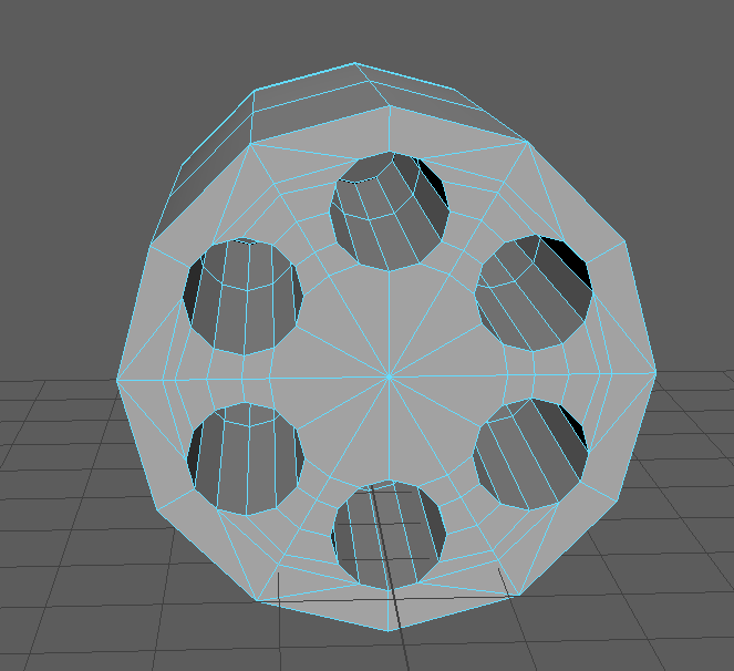
Here's how the revolver looks so far. There are still many things that need to be done to the chamber, but this is how it looks before being smoothed.


In future, I will also need to edit the indent I made in the frame, as it doesn't quite fit the positioning of the slots. However, I decided I'd fully delve into this task at a later date.
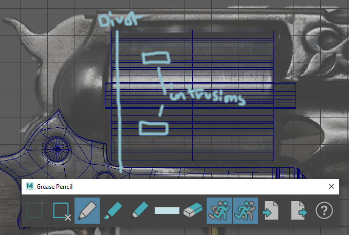
I decided that I wanted to try and add the divot and intrusions into the chamber. I decided that adding edge loops would be the easiest way to do this, so I had a go. Unfortunately, since this geometry wasn't originally a cylinder, I would have to make individual cuts all the way round the outside, which would be highly time consuming.


Instead, I went went to an earlier save and added the edge loops there. I decided to only create the divot and not the intrusions, as I felt they would be easier to add in the form of normal maps.
I then duplicated, combined and merged the geometry again, and set to work on creating the divot. I used the two other edge loops I'd created to make sure the rest of the chamber keeps its shape. I selected all the vertices on the central edge loop and pulled them inwards before bevelling the outer two edge loop. Once I'd done this, I bevelled the rest of the chamber by 0.02 with two segments.


Here's how the revolver looks now with the divot.


I decided to go back and correct the geometry on the top and bottom of the chamber. This meant going back to a previous save without the bevel and working forward from there. I started adding line edges to the geometry and moving the vertices out to be more even.


I added a few more lines, with the intension of deleting the old lines and filling in the gaps.


I started deleting faces and then filing them. There was also the job of moving and merging the vertices to make sure everything was in quads.
Here's what I managed to achieve with creating cuts and bridging the holes.


I then duplicated the cylinder and then deleted the faces on the top. I then used another copy of the chamber and deleted everything else. Using the top I cut out, I mirrored it over to the side I'd deleted the faces off of. I then combined and merged them together so that both sides of the chamber had the correct geometry on both sides.


I quickly bevelled the chamber again, which completes it for now.


Here's how the revolver looks now. With the chamber completed, it looks far more finished than it did before.

I decided now was a good time to move onto some smaller tasks, like correcting geometry and making it more accurate. I duplicated the entire geometry and so that I would have a copy of the original if anything went wrong.


I decided to go back and correct the handle connector first. I felt this was fitting, as this was the first model I created for the revolver. I started by deleting and bridging the faces of the two sides of it, as the gap left in between the geometry didn't look right. Now, the only hole in the geometry is for the trigger to go through.

I planned out where I would add in edge loops with the grease pencil tool, which I will then adjust until they match the smoothed geometry.


I added in a few edge loops and then went into the smoothed view to adjust the new vertices.


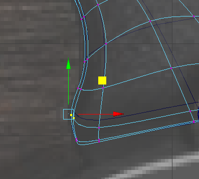
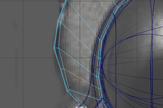
I added some more edge loops, and then went to the insides of the pipes and selected all the new vertices. With them selected, I sized them down to fit with the curve of the original circle. I did this with the other hole as well, and then adjusted any vertices around the outside curve to match the reference.
I also added edge loops to the curve that connects to the handle, and adjusted them to match the curve better as well.

Here's how the metal connector looks now with the increase in edge loops.


It looks one thousand times better, and textures will now look far better when made and applied.

With the corrected geometry, this is how the revolver is looking so far.


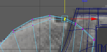

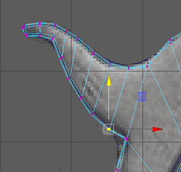


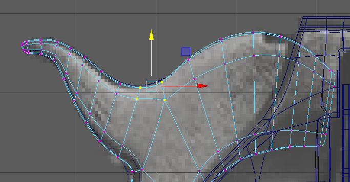
With the same idea, I went and edited the hammer. I started this by adding all the edge loops in and then moving them around in smoothed view to create the same I had when there were less vertices.


I found a few vertices that overlapped, so I moved them into more suitable positions to even out the geometry.


Here's how the hammer looks now. Unsmoothed, it retains far more of its shape than it did before when it had less edges.


Here's how the revolver looks after another day of modelling. With the chamber made and some of the geometry fixed, I'm well on my way to finishing this model. The next things I will model are the screws for the connector and handle. After that, I will start thinking about sizing up the rest of the models to fit with the barrel.


Comments