3D Modelling a Revolver - Part 6
- Nov 13, 2020
- 4 min read
With the majority of modelling complete for the revolver, it was time to start adding to the existing geometry.


I starting with the frame of the revolver. Much like with the metal frame, I added some edge loops to the cylindrical section and expanded them outward.


I corrected some of the vertices in the curve as well, as they were clipping through the rest of the geometry.


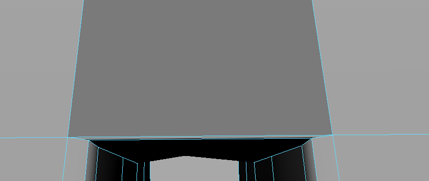
Here's how the frame looks now. It's far smoother thanks to the edge loops.


I also worked on expanding the separate pieces of the revolver outwards to fit the barrel. The last thing I expanded outwards with the handle, which I decided to work on later.


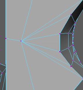
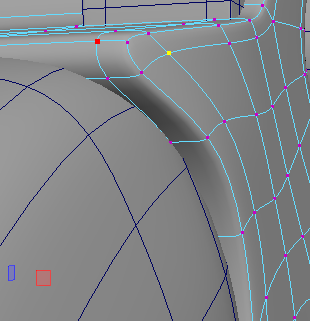
Going back to the frame, I worked on the semi-spheres that surround the top of the chamber. Since the dip still needs to be worked on. As it stands, a bullet cannot realistically fit through the gap and into the chamber, which is something I want to fix.


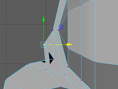
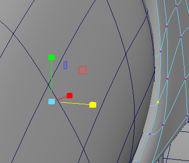
I started by pushing the inner vertices inwards and adjusting the rest of them.


I decided it was time to model the final part of the revolver; the screws. Since the screw will mainly be hidden, I scrapped the idea of extruding it outwards to create the shape.


I instead added some subdivisions to the caps of the cylinder and then pulled them outwards to give the screw a curve.


I then used the multi-cut tool to create a dip in the centre of the screw. With the area selected, I extruded it inwards.


I then had to fix up the geometry, since some of the vertices had been moved. I added some multi-cuts to the geometry and merged the vertices together.


With the vertices merged, I selected the edges and bridged the gaps. I used the multi-cut tool once more to correct the geometry.


I then bevelled the edges and then duplicated it and and sized it down to fit in the smaller hole.

Here's how the metal connector looks without the gridlines. It's starting to come together, although the screws are slightly shaky when smoothed.


I went back to the handle to remove the intrusion I added weeks ago, as I decided I didn't want a screw on the handle anymore. I did this by deleting the faces inside and at the edges of the hole, merging the vertices caused by the bevel, and then bridging the hole. I did this on both sides.


With the hole gone, I straightened and evened out the vertices on the handle, which made it far smoother.


With the handle fixed, I decided to have another attempt at creating a screw.


I made another cylinder, but this time turned off the subdivisions on the caps, and drew the lines on with the multi-cut tool instead. This worked out well, since the cuts ended up creating five polygons.
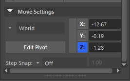
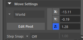
I then set up some edge loops and checked their coordinates to see if they were even. Since the cylinder is centered, I just had to add or get rid of a minus to get an equal amount of distance between them.


This time, I deleted the faces at the sides, as they would be deleted anyway. I then extruded the central faces inwards and snapped them to the edge loops I created. I then snapped the vertices to the edge loop I created and merged them together.


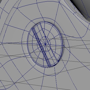
I then bevelled the edges, which went slightly square because of the geometry. However, this is mostly hidden inside the rest of the mesh. I duplicated the screw and sized it to fit in the other hole, this time with a small rotation to make them look like different models.


Here's how my second attempt at the screws look. They are far flatter than my original attempt, but I like how they look with the rest of the model.


Here's how the revolver looks now. There's only a few more things I need to edit before I can move onto UVing and Texturing my model.


One of these things is filling any holes and gaps I left in the model. Going back to the metal connector, I deleted all the faces on the inside, but still left the gap for the trigger to poke through. I then bridged the gap I made and reconnected the bevels to each other with the multi-cut tool.


Here's how the metal connector looks now.


Now, I moved onto some of the other details I'd yet to add.


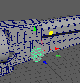
One of these details was the cylinder I'd placed in the chamber to connect it to the rest of the revolver. I hadn't yet bevelled it, so I did this before moving onto the next thing.


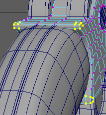
I revisited the spheres on the frame, and fixed all the vertices that were sticking out. I even pulled back the vertex that connects all the mutli-cuts together, giving me more room to push the rest of the mesh back.


I managed to push it back by quite a lot, so I decided I was happy with this part of the revolver, although I may come back and edit it more later.


Lastly, I went back to the metal connector one last time and pushed in the corner vertices, as I didn't like how sharply they stuck out from the handle. I adjusted the edges around the handle to make a better curve, and then disbanded the corner vertices together to 'pinch' them in closer to the handle. I quickly adjusted the other vertices before I was happy with the results.

I'm now in a good position to start thinking about UVing my model, although there are a few small things that I need to adjust first. However, I'm incredibly close to being able to move onto the next phase of the revolver: UVing and texturing.


Comments