3D Modelling a Revolver - Part 1
- Sep 28, 2020
- 8 min read
Updated: Oct 4, 2020
As previously mentioned, one of the 3D modelling tasks of this year is a revolver, which I previously planned out in a post. After thinking more on it for a few days, I decided to just jump in a try new things out, since the easiest way for me to get comfortable with something is to test out new methods.
Thankfully, since I'd already thought a lot about the process of creating a revolver, it wasn't hard for me to decide what to start with.
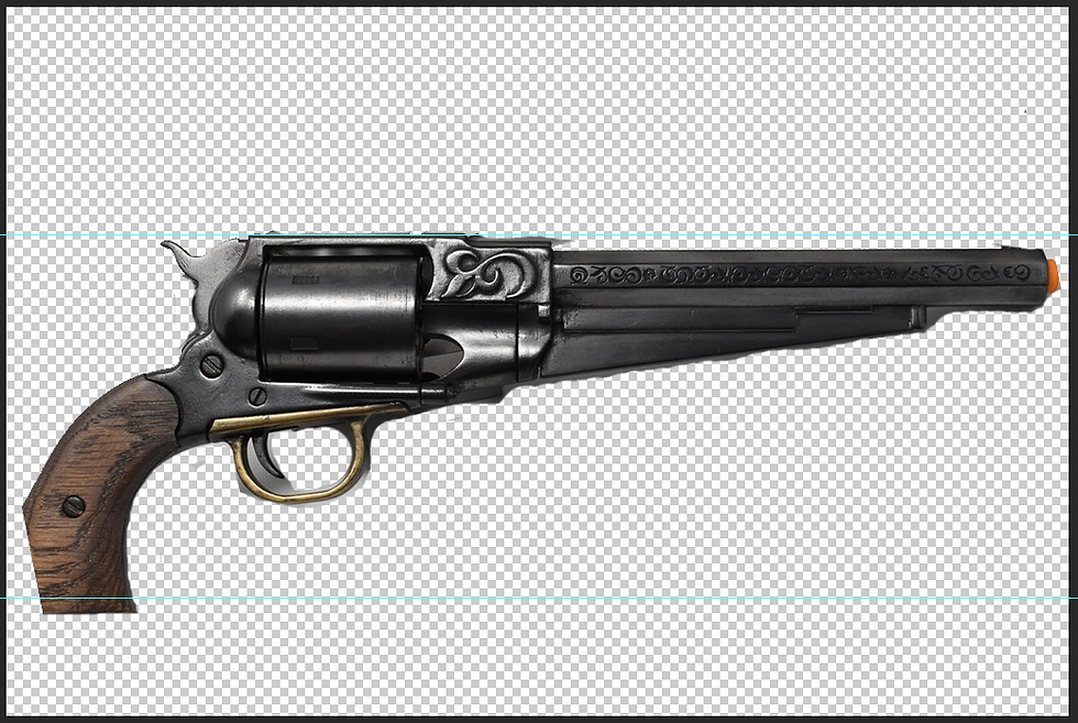
Before I properly started modelling, I cut out a rough version of the revolver I used as reference and to test out how the geometry would work. I lined it up with two margins, and then removed the background.
Since the perspective of the revolver is slightly off, I'll just be using this more as reference, and not modelling directing after it. Since it's a fantasy gun without a confirmed real life counter part, its alright for me to make some changes. So long as I stick to my concept and idea of what they should look like, I don't see a problem with changing the design a bit.


After I brought it in as an image plane and set it to a reference layer, I added two poly pipes and moved them into position. Like I originally planned, I decided to create the metal connecting the trigger to the chamber and handle. I decided to use pipes as they have a hole in the centre, which will be used as a gap for the screws.
I made sure the two had the same height and subdivisions so that they can be easily attached. They each have 6 subdivisions, as six was the lowest I felt I could go, while still being able to keep the shape while smoothed. Once I was happy with the size and shape of the pipes, I deleted the all their faces but the ones facing above in the same way that I created the wind-up key before. This is a strategy that I plan to abuse, as its a highly effective way of modelling a lot in little time.


I combined the two objects and then merged them together so that they were joined with two vertices. Once I'd made sure they were merged fully, I started adding adding in more faces to create the rest of the shape of the piece. I did this by extruding the edges outwards in the side view in Maya.
I ran into a few problems, as sometimes I'd have trouble combining vertices from the extrusion. It took me a few tries to successfully create the faces above the pipes, as any vertex I had accidently missed would set me back a few steps. I managed to figure it out, however, and then extruded the bottom part of the geometry down to where it meets the handle, I ran into a small problem with curve, but I decided that when I added in the bevels around the edges that I'd adjust some of them to better accentuate the curve of the metal.
I also added in an edge loop to the centre of the extrusion, which I adjusted to fit the shape of the metal. I had to make sure I didn't confuse where the top of the revolver is, as the image reference is at a slightly upward angle. I also took the time to space out the vertices from each other to even the geometry up.


Once I was happy with the adjustments, I extruded a final face off the left side to go under the chamber. I alternated between smoothed and unsmoothed to make sure I modelled it to the best of my ability. Because there were two sections to the extrusion, I decided not to add any edge loops right away.


With the faces complete, I selected the geometry in object mode and extruded them out to the same height as the poly pipes originally were. I decided that I'd over estimated how thick this section should be, and sized it down from 2.11 to 2.00. I felt that this made it a bit more lithe like in the reference image.
I bevelled the edges, keeping an eye on how it would look while smoothed, down to 0.32 with 2 subdivisions. Since the edges of the metal are sharp, I made sure to hold Ctrl down while dragging to make sure I could eye it more precisely.

This is what the model currently looks like, unsmoothed.

I decided to use the grease pencil to plan my next move instead of just rushing in. Since I needed to add edge loops to the extrusion, I planned out how many I thought I would need. Since there's a small divot in the metal, I decided that I should place this one free-hand before going into the extrusion menu and changing the settings to place the equally and automatically.


I did just this before adding three more subdivisions to the furthest right extrusion. I realised at this point that this part might be attached to a different piece of metal on the revolver, so I'm not sure whether to delete it or not. However, I decided to leave it for now, as I could decide this while modelling the metal piece behind it.
I went up-close to the free-hand edge loop I placed and added two more next to it. I then selected the centre edge loop and disbanded it inwards. Once I was happy with this, I bevelled the other two edge loops to help it keep its shape.


For now, this section of the revolver is finished. As a final touch, I adjusted one of the vertices, as I felt it wasn't spaced correctly. I made sure to select before side of the shape when I made the adjustment.
I'm definitely planning to cut part of the extrusion off, and also to try and flatten it as it follows to barrel of the gun down to make it more aesthetically pleasing. It also give the revolver a more streamlined feel, as this part of it won't just be flat. However, this would've been done easier if I hadn't already inserted the edge loops onto it. But I could still use the extra vertices to my advantage, and create a more interesting shape than a gently decline.

So, with the metal connector section complete to some degree, I decided to plan out how other things would connect to it. Since I need to model it in components, I will most likely have to make changed to the bottom of it to accommodate the trigger. I've decided that I will do this after modelling the trigger, so that I can easily snap the existing geometry to fit with the trigger.
However, I decided that I didn't want to move onto the trigger just yet. I decided that the next thing I modelled would be the handle of the revolver.


I saved the metal connector into its own separate layer before adding a cube and sizing it to the same measurements as the poly pipes. Since the handle has to fit inside, I sized it down a bit before moving it down to the base of the handle. I used a cube with the same thickness as the metal connector to help with this, as I'd set that layer to invisible for the time being.
This was hard to eye-ball, as the image I used as reference was cut off at the corner. I did my best to get the size right, before deleting all by the top face.
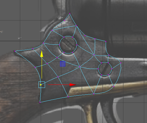
Using the same technique, I extruded the edge up and rotated it to match the curve of the handle. I then added 6 edge loops and adjusted all the vertices in smoothed mode to create a convincing curve. I lifted the bottom two vertices up, as that was how it was in the original image. Although this could be taken as a manufacturer error, I liked the idea of this revolver having a few flaws to it. In my opinion, flaws can add character to a model.


Once I was happy with the the shape, I started adding the curve to the front of the handle. Since it's wooden and designed to be held by a human, the handle needs to be rounded to accommodate this.
My original plan was to push the vertices up, but I decided to instead push them down so that I could keep the position I had with the front faces. Once I'd checked the moved the vertices around to even them up. I also decided to try and create a hole for the screw to go. To do this, I moved four of the points into a cube around the screw to come back to later.


The next thing I did was extrude all these faces outward. I realised at this point that I should've done this before curving the front of the handle. It was an easy fix, but it was time consuming. I'm still learning how to model, so I'm not overly surprised I'm making mistakes like these. These mistakes are actually what help me find shortcuts to model.


I extruded the square I'd created inwards, and bevelled it. I may get rid of this in future, which shouldn't be too hard and should only involve a small amount of recreating geometry.


Once I was happy with how the handle looked, I mirrored and combined it to create a symmetrical shape. I merged the vertices before bevelling the edges. I then went all the way round the model and evened up the vertices, which had been shifted off by the curved I'd added as well.
This took a little while, but I finally got all the vertices around the sides to the same coordinates. I had to do this because of the metal wrapping around the handle. I duplicated the model and made it its own separate layer so that it would have the same measurements as the handle itself.


The next thing I did was extrude the central faces around the edges inwards, and bevelled to make room for the metal accents. I made the bevel for the extrusion's edge far harsher, as the outside of the handle has most likely been worn down by being used, and is also made of wood, so having a sharp edge would be uncomfortable to whoever used it.

So far, this is what exists of the revolver so far. The metal connector looks uneven because it needs to duplicated to the other side of the scene. I also need to make changes to it, so there would be no point mirroring it right now.
Since I already have the main part of it ready to go, I decided to model the metal band of the handle.


I removed all the faces apart from the edges of the sides. The vertices were also slightly out of line on this, so I went around and moved them back into position. Once I'd done this, I checked it in comparison to the other models, and saw that it fit right it.


I extruded the faces inwards, which unfortunately placed the geometry inside out. To fix this, I selected it in object mode and went into the mesh menu and inversed it, which turned it back to the right way round.


I bevelled it by a small amount and then added the wooden part of the handle back in to check it. I also used this model to extrude the metal component to the correct size.

This is the entirety of the revolver model so far. I'm proud of what I've accomplished in such a short amount of time. I made sure to save all of this into a project file and increment and save when I got the chance.


For one day of modelling, I'm incredibly proud of what I've achieved. As someone who isn't strong in their modelling skills, I think I'm starting to get the hang to modelling intricate shapes. I'm glad that I'm able to recognise my mistakes far easier now, as it helps me think of solutions to them, and also to avoid making them again in future.
So far, I think I am doing very well as 3D modelling a revolver. I next plan to model the trigger and the hammer at the back of the revolver (which is used to open the chamber/cylinder). The trigger will be modelled from a pipe, and the hammer will be modelled from a cylinder, and then extruded outwards. I hope this process will be made easier by what I already have modelled.


Comments