Maya reminder - Modelling a Wind-up Key
- Sep 18, 2020
- 10 min read
Since I’m a returning student to Nescot, I already know bits and pieces about 3D modelling from the NextGen: Level 3 (Games, Animation and VFX) course I have already completed. However, 3D modelling is one of my least practised skills. We were given a small, warm up exercise in which we modelled a wind-up key with the guidance of instructional videos. It was a great way to jog my memory of the different tools and techniques I learned in Autodesk Maya during the last two years.


We started out with two reference images to work from. The top-down view was used as the reference image we’d have on a plain in Maya.
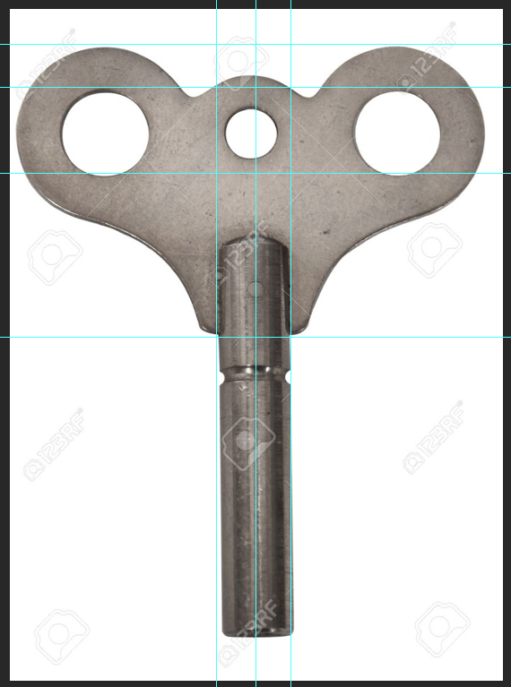
Following the instructions, I brought the image into Adobe Photoshop to create a better image to use as a reference. The first thing to do was to line it up and check it was straight. The easiest way to do this is to go to ‘view’ on the top toolbar and select ‘visible rulers,’ which will make it so the rulers are showing on the X and Y axis. Then, I clicked and dragged ruler lines out from each one and lined them up with the holes in the handle horizontally, and vertically with the pipe.
I noticed that the wind-up key itself seemed to be asymmetrical, which was probably just how it was manufactured. I corrected it as much as I could, although this led to the picture being off-centre and the pipe being slightly crooked. However, while modelling, the wind-up key will be modelled straight, so having the simplest part of the wind-up key off-centre isn’t a problem at all.


Because it has a white background, I used the magic wand tool to erase it. I also made sure to shift-click on the three holes, so they’d be erased as well. I checked the edges to make sure nothing had been deleted in the erasing, which thankfully it hadn’t. With this done, I could save the image and import it into Maya.


I went into the top-down view in Maya and added it in as an image plain. I then turned it into a reference layer and turned down the visibility so that it wouldn’t be in the way of modelling. So, with everything ready to start modelling, I made sure to create a new project folder for my work, and then set the project to it to ensure my work saved in the correct place. This also meant I could keep the references inside, so that Maya would know where to find it.
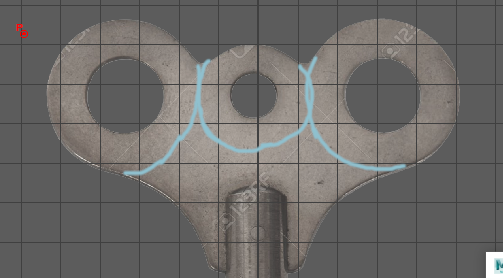
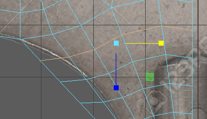
So now that the image plain was set up, I used a grease pencil in the top down view to draw out where each of the shapes would go. My first instinct was to use a cylinder and eliminate a section in the middle of it out. However, in Polygon Primitives, there’s also a pipe, which was far more appropriate because of the hole it already had.


So, I brought a pipe into Maya and moved it into to position. Pressing T, a small menu opened. With this, I sized the pipe up, holding down Ctrl to have more control over the sizing, as the wind-up key is a very precise shape. With the size correct, I made sure the hole was the right size as well. Since the key was manufactured imperfectly, and modelling means things can be done perfectly, I left its position alone.


I then created another pipe in the same way for the central hole in the key. I made sure to match the heights of the two pipes, as they needed to be perfectly level. I went with 0.3 for the height, as the handle of the wind-up key is very thin.
As an experiment, I added two subdivisions on the height of the pipes, and smoothed them to see how it would look. However, I got rid of these, as they would be deleted later. With the two pipes at the same height, all that was left to match up was the sides. As they needed to be combined, I had to make the edges of the pipes match up before I did anything else.
So I kept the first pipe at 10, and then brought the send down to 6, as it doesn’t need as much detail because it’ll be sandwiched in the middle of the key. It also has to be an even number, as I need to bridge with an even amount of faces otherwise it won’t work.


With both the pipes made, it was now time to prepare them to be mirrored to create a perfect wind-up key. I isolated the view to the first pipe, and started deleting the sides, inside rim, and bottom, until the only faces that remained were pointing upwards.


I then did the same with the smaller pipe, and then combined both of them into one object. I selected the three sides facing each other and bridged them together. I then went into the top-down perspective and turned on wireframe mode, which allows me to only see the edges of a model so that I can work from reference. With the two bridged, I pressed 3 to smooth the shape to get a glimpse of what it will look like when completed.


I moved some of the vertices to better fit the curve of the key handle, and then checked it in without smoothing. I then extruded faces from the lower edges to start creating the rest of the handle. I straightened all the edges by checking the coordinates of each one, as I couldn’t snap it to the grid, and the reference image was off-centre, something that I could easily fix later, but unfortunately made this a lot harder. I had to make sure everything lined up perfectly before I could move on. Thankfully, it’s possible to snap to vertices, so I turned this feature on to speed up the process.
An alternative way I could’ve done things with level all the lines with the grid, select them, and then moved them all up in line with the bottom edge of the key’s handle. However, since the result was the same, it doesn’t matter too much. The next thing to do was add edge loops to better maintain the shape of the handle. To do this, I opened to the options for edge loops, and selected ‘Use Equal Multiplier,’ which made it so the edge loop will always be the centre. I then did the same thing with the lower section, but went up to five with this one.
It then a case of selecting each row of edges and shrinking them down to match the curve of the handle. The way to do this is click the pivot point of a model and hold down ‘D,’ which allows you to move the pivot point of it. Then I also held down ‘X’ to snap to the grid, which meant the inner part of the key wouldn’t be affected by the resizing. Unfortunately when I did this, I forgot that I had not yet moved the geometry to the centre, which meant I had to restraighten the inner edges.


While moving all the edges in, I decided that the bottom curve needed more attention, as it wasn’t looking right. I installed two extra edge loops in between the bottom two edges to enable me to get the detail of the curving edge correct. I made sure to work with smoothing on to see the full effect of my decision.


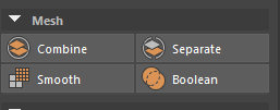
With the curves corrected, I selected the geometry in object mode, and snapped the pivot point to the straight edge of the inside. I then centred the handle and mirrored it over on the X axis. However, the two sides weren’t attached, so I combined them. This still doesn’t fix the problem, but it leads to the solution. I went into the top-down view and selected all the vertices down the centre and went into the Mesh menu, and selected ‘Combine Vertices.’ This combined the vertices and meant that they no longer move separately.


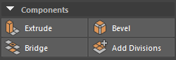
Now it was time to give the handle more depth. I selected it and extruded it. I made sure to extrude it the right way, otherwise the geometry will be inside out and appear black. I made sure it was the same height I’d given it in the first place (0.3). The pivot point has been reset to the middle by default after being combined, so all it takes is turning on grid snapping and moving it back down to the origin to centre it.


Now all that was left to sort out for the handle was keeping its shape when smoothed. I tried out inserting two equal edge loops around the sides, but this didn’t match the sharper edges depicted in the reference images. So instead, I selected all the edges and bevelled them to sharpen the edges. With the edges bevelled, it became far sharper, and much more like the reference image.


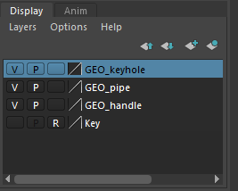
The last touches I added to the handle was applying the ‘Blinn’ material to it to give it a shine. This meant I could get a better idea of how it compared to the real thing. I also selected the handle and gave its own layer so that I could go on to create the rest of the wind-up key.


It was now time to start creating the pipe of the wind-up key. To start off, I turned the visibility of the handle layer off so that it would be easier to work from the reference image. I then added a pipe, rotated it 90 degrees and stretched it out to run the length of the pipe. I also thinned out the thickness of the pipe to ensure that I would be able to model the final part of it inside later.


I made sure to bevel the edges of the pipe so that it kept its shape, since smoothing something so thin drastically changed its shape. Further up the pipes, I also added two edge loops to make the divot it has halfway up. In the middle of these, I changed the settings once again to be able to place an edge loop directly in the centre. Taking this central edge loop, I resized it smaller, while also making sure I didn’t accidently overlap with the inside. Unfortunately, I had to add bevels onto the sides to help keep its shape better when smoothed.


The next thing to do was create the upper part of the pipe where it connects to the handle, which ends in a slight dome. To prepare to add a dome on, I deleted the top faces and then pushed the inside part down and filled the hole left and bevelled it. Since it won’t be visible from the outside, the importance of this isn’t that high.


Now I had to create the dome. I added a sphere, resized it to the same measurements as the pipe, and then moved it up so that I could work with it more easily. I also rotated it so that it matched the edges of the pipe.


I squashed it down so that it wouldn’t be so dramatic of a dome and would fit better with the reference image. I also lowered the segments it had, as it doesn’t need to much detail and will be smoothed out anyway. I did all of this before deleting the lower half of the sphere and then merging the vertices the same way I did before. All that was left to do was bevel it so the top of the pipe wouldn’t become one big curve.


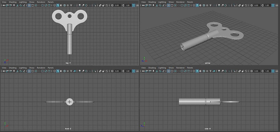
I applied Blinn to the finished pipe and put it with the handle to compare it. Since they both fit in with each other and I couldn’t find any problems with them, I moved onto the final part of this project.
After having saved the pipe into a separate layer like the handle, I moved onto the final part of the wind-up key. I created another pipe and moved it inside of the previous, making sure to size it down so that it sat comfortably within it. Once that was done and I’d elongated and pushed it inwards to a good position, I added a cube and sized that down as well.


Since the reference image has a square key insert inside the pipe, that’s what I was going to create. Moving the vertices to each point in a straight line would be time consuming and pointless, so (still following the video tutorials) I added edge loops directly at the corners of where the cube was. Since the pipe I was using had an even number of sides, it was easy to just click and have the edge loops exactly where I needed them.


All that I had to do now was select all the faces on one side of the cube, flatten them out with the resizing tool, and then move them forward so that they rested against the cube. I repeated this for all four sides before removing the cube to see my handiwork.


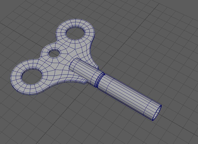
All that was left was to bevel the edges to keep the shape, which was extra important for this part of the wind-up key because of the sharp square. With that done, I saved it in the same way, applied Blinn to it, and then brought them all together.


All the models together look amazing, and I’m incredibly proud of myself to have stumbled through this task so successfully. I expected to run into far more problems and to take far longer to complete it, but I managed to finish this in around two and a half hours. I did, however run into a few problems along the way to do with settings. For example, it took me about five minutes to work out why the handle wasn’t mirroring correctly (it was a problem in the settings menu, in which it was set to combine straight away). However, I managed to fix this without any assistance.
Modelling has always been my weakest skill. It’s something I haven’t done a lot of in the past few years. This task was a great reminder of what tools I have at my disposal in Maya, and how I can use them in simple ways to make a model better. It was also a great chance for me to learn easier and more efficient ways of modelling, as the only ways I knew before were time consuming and didn’t always have to best results. Doing this on the first day back was a great confidence boost to my 3D modelling skills, which I have neglected to hone.


In conclusion, I think I did well at this task considering 3D modelling is something I haven’t experimented with properly. It’s opened my eyes to just how many tools there are in Maya, and how I should load up the software and have a go with them. This small project was also a great memory jog, as it helped me remember the quick shortcuts I remember (such as grid-snapping, bevelling and extruding).
The most important thing I realised while doing this project was that 3D modelling is something that needs to be planned thoroughly before being attempted. If I’d been presented this project, I probably wouldn’t have had a clue as to how to go about it. Next time I get a project for modelling an object with the same complexity in shape as a wind-up key, I shall try and separate it into different pieces. From there, I can work out what primitives I can use to better create the shape, like the pipes for the holes in the handle. I think this will make modelling far easier for me if I plan everything out before beginning, so that I don’t just model blindly. This will also save me a lot of time, since I can only use this software will at college, and can plan effectively at home before arriving instead of wasting time doing that there.
In future, I look forward to modelling again, as I now have a good strategy that I feel will work a lot better for me. I look forward to the rest of this years modelling tasks, and how they will all tie into each other, as well as the end result.


Comments