Creating a 3D scene with Nuke and Maya - Part 1
- Dec 3, 2021
- 5 min read
Before sculpting truly begins, I need to set up some camera plates to put my plant into. To do this, I need to use both Nuke and Maya.
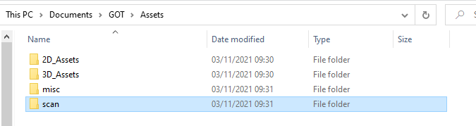
I started by setting up a folder structure, including various files within the Assets folder, which will all be used for different things I create and download for this project.

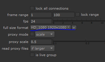
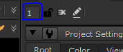
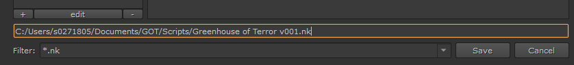
In Nuke, I started by changing the directory and saving up my project in the scripts folder I'd made. I also changed the format size to 1920x1080, and changed the total amount of tabs I could have open at once to 1, so that the panel doesn't become unreadable.
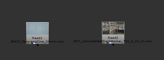


I started by reading in a checkerboard and the plain footage of the greenhouse, and putting them inside their own backdrop node. I made this node greyscale so that if I wanted to do any colour grading, there would be nothing there to disrupt my interrpretation of colour.


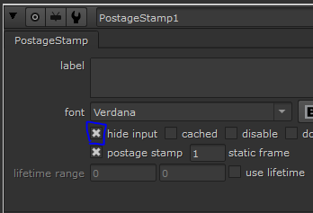
I also added two dots in the file directory, which makes it more readable. I also added some postage stamps of the checkerboard and footage. I then hid the inputs of the postage stamsp so that the node graph doesn't become unreadable later on.


I started by adding a frame range node, since the beginning and end of the footage are a little shaky.
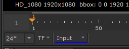
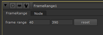
I changed the frame range to 40 - 390, and then changed the viewer to display only the input amount of frames.


I then reorganised the layout of Nuke to make it easier to work with. Since I will be working mostly with the Node Graph, I wanted this to be the largest panel on screen. To do this, I started closing panels, and then moving them around. I kept the tabs in the same position, but moved the viewer to the bottom right corner beneath it. This leaves the rest of the screen for the node graph, which is what I wanted.


Beneath the Frame Range node, I added in a Merge node, and a point node, which will make connecting pipes a lot cleaner to look at. I then added a Backdrop node in, and added a postage stamp of the checkerboard from earlier.
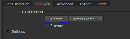


I then added a Lens Distort node, and used the checkerboard (which was filmed on the same camera with the same settings as the footage) to create an undistorted camera plate.

Here is how the node graph is currently looking.


Here is the undistorted footage next to the original. Thanks to the checkerboard being undistorted, the footage can now be undistorted as well.


I then added a Camera Tracker Node, which will identify points of which to track the footage in 3D space. Since I'm going to be working with footage that I have information about, I added a sticky note with all this information on it.
This would be required in a company, as multiple people could be working on a shot. It's important that this information is in the same place as everything else needed for a project.


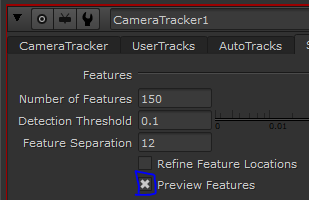


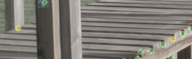
I then opened the Camera Tracker node and filled in all the information on the sticky note node, along with identifying that the footage had no lens distortion. I then turned the preview of these points on, and tracked the footage.
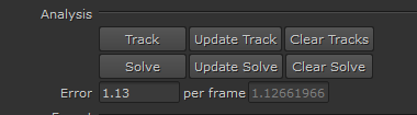


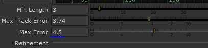
I went into the AutoTrack menu and erased any nodes in the red, which were tracked incorrectly. I made sure the Max Error that could pop up was 4.5.


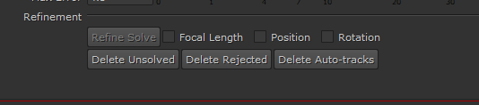


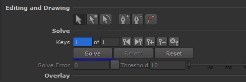
I then solved the track, and deleted any points in the red, which gave me a better solve.


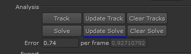
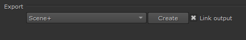
As I whittled down the number of errors from the track, I was making sure to update the Solve. Once I was somewhat happy with the track, I went into the Scene tab and then exported it as a Scene+.


This created a 3D scene node group, which is what I need to use next in order to be able to use the tracking nodes in 3D. I took a few minutes to neaten up the node graph, as it was becoming untidy.


I then had a look at the track in 3D. I had an issue with being unable to see the tracked points unless they were selected. I had a quick look in the preferences menu, but couldn't find anything that could cause this. Maya was already set as the 3D control type, so there wan't a cause to this issue.

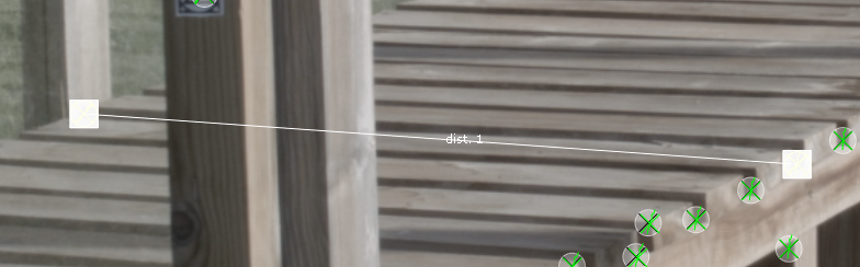
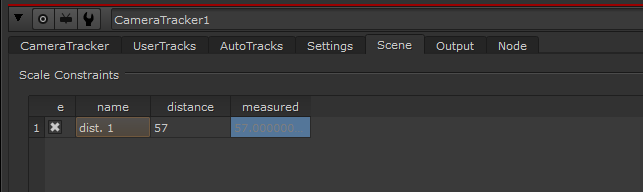
I decide to just grin and bare it, and started setting up the scale of the 3D space. This will mean that any model that goes into the track will be the correct size. I selected two nodes on opposite sides of the workbench then added a distance tracker between them. I then went into the Scene node and set the distance between the nodes to be 57cm.


I then added in another distance tracker, this time measuring the length of the workbench. This will ensure that when I put a plant on the workbench that it will be the correct dimensions. I then set the back left corner to be the origin of the 3D scene.


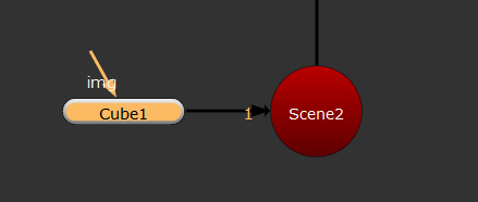
Off of the Scene node, I connected another one, and then added a 3D cube node to put in some proxy geometry to prepare for adding a 3D asset later on.


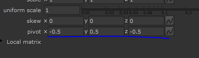


In the 3D scene, I adjusted the pivot of the cube to be in the top left corner. I also tried to solve the problem I was having with the tracked points not appearing clearly, and tried to add a point cloud node. However, I felt that this made the scene harder to understand, so I undid this.


I then set about sizing the cube up to match the workbench in the scene, which had been measured before we filmed the scene. This made the process of lining up the cube a lot easier.
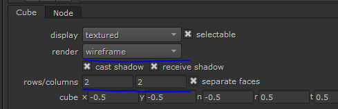


I changed the render to be wireframe so that I can more easily see the footage through it. I also set it to 2 subdivisions, which made it far simpler to work with. I ended up having to move the shape around from the origin, which I felt fit in with footage more.


I then duplicated the cube and named it Cube1_BACKUP just in case I wanted to go back and edit that particular version of it.


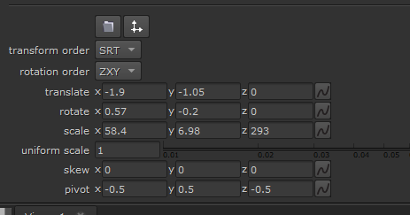

Here is the final version of the cube, along with the position, scale and rotation values that I settled on.


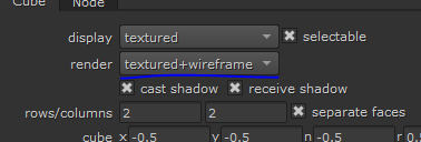


I then added in a Checkerboard Node and applied it to the Cube, which will give the cube a checked texture. To display this, I changed the render to be textured and still show the wireframe.
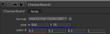


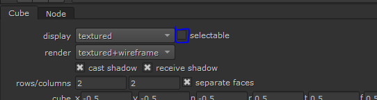
I went into the Checkerboard Node and changed the size of the texture to be 500 by 75, which looks a lot better on the top faces. I then turned off the selectabilitiy on the workbench cube.

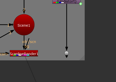


I then linked up the Scanline Render Node to the Merge Node I set up at the beginning.


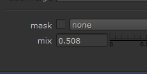


I then rendered out my progress so far, with the proxy workbench still translucent so that the footage behind is more visible. This beings me to the end of my progress for now. There is still the phase of moving this 3D Scene into Maya, which will be my next task.


Comments